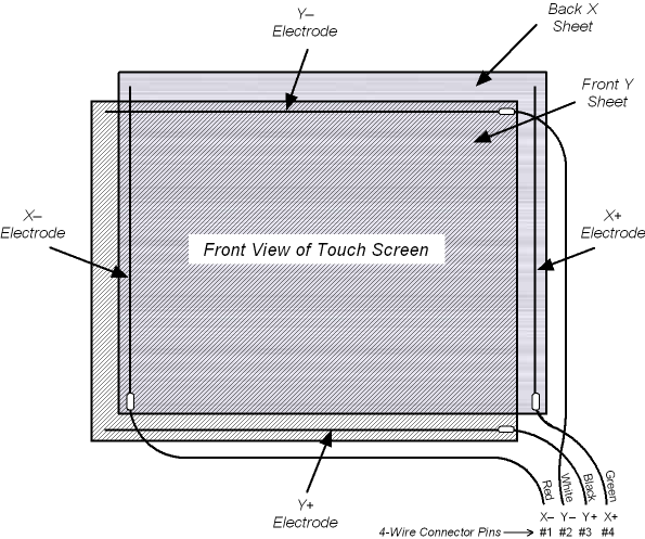
The red and green wires are connected to the X - and the X+ electrodes, respectively (X - on the left edge of the board; X+ on the right edge)
The white and black wires are connected to the Y - and the Y+ electrodes, respectively (Y - on the top edge; Y+ on the bottom edge)
On all front projection interactive whiteboards the X electrodes are on the back resistive sheet and the Y electrodes are on the front resistive sheet.
|
pin 1 |
= |
red |
X - |
|
pin 2 |
= |
white |
Y - |
|
pin 3 |
= |
black |
Y+ |
|
pin 4 |
= |
green |
X+ |
Use this diagram while troubleshooting your 500 or 600 series front projection SMART Board interactive whiteboard.

The connection to the serial controller